Current Research in Real-time Sound Morphing
Loris analysis/synthesis by Kelly Fitz and Lippold Haken.
Real-Time Sound Morphing by Lippold Haken and Symbolic Sound Corporation.
Continuum Fingerboard invented by Lippold Haken.
Lippold Haken first posted this article in February 2000, updated November 2003, then minor edits.
This article describes one of the synthesis algorithms we developed to work with the Continuum Fingerboard. The algorithm is described in six sections:
Sections 1 and 2 introduce Envelope Parameter Streams and the real-time additive synthesis that we have implemented with Symbolic Sound Corporation for their Kyma Sound Design Workstation. A reduced set of features is also implemented for the Continuum Fingerboard’s built-in EaganMatrix synthesizer (version 8.81 and later).
Sections 3 and 4 describe our use of Bandwidth-Enhanced Oscillators and Time-Frequency Reassignment, available as open source Loris.
Sections 5 and 6 introduce Timbre Control Spaces and describe how they can be used to control sound morphing.
The final section is a list of papers referenced in this article.
1 Introduction to Real-time Additive Sound Morphing
Together with Symbolic Sound Corporation, we have implemented an additive synthesizer that we like to use with the Continuum Fingerboard. The additive synthesizer is implemented in real time using the Kyma Sound Design Workstation (Scaletti 1987, Hebel and Scaletti 1994). Compared to sampling synthesis, additive synthesis is attractive for the Continuum Fingerboard because it is well suited to continuous timbre control.
A sampling synthesizer uses a set of source recordings to synthesize an acoustic instrument. When the performer plays a note, the recording corresponding to the performed dynamic and pitch is played back. Notes for which there is no source recording are synthesized by playing a "nearby" recording at a modified amplitude or frequency. A shortcoming of the sampling technique is the inability to produce the spectral changes associated with finger x, y, z movements during a note. Simply varying the amplitude and frequency of a recording is not adequate.
Additive synthesis, on the other hand, represents each sound as a collection of sine wave components, or partials. It allows independent fine control over the amplitude and frequency characteristic of each partial in a sound. As a result, a wide variety of modifications are possible with additive synthesis, including frequency shifting, time dilation, cross synthesis, and sound morphing.
We have developed a real-time additive synthesizer that works well with the Continuum Fingerboard. Like a traditional sampling synthesizer, our additive synthesizer uses a set of source recordings, but unlike a traditional sampling synthesizer, our additive synthesizer models its source timbres as collections of bandwidth-enhanced partials (sine waves with noise) with time-varying parameters. These source timbres are manipulated in real time to produce synthesis timbres.
In order to implement efficient real-time timbre manipulations, we developed a stream-based representation of partial envelopes. Envelope parameter streams are the counterpart to sample streams in sampling synthesis. They provide amplitude, frequency, phase, and noise envelopes for each partial. Bandwidth envelopes represent noise energy associated with each partial and constitute an important extension to additive sine wave synthesis. We developed noise envelopes so that we have a homogenous representation of both sinusoidal energy and noise energy of a sound.
The Continuum Fingerboard tracks the x, y, z position for each finger. The synthesizer maps these positions to the timbres of the source recordings using a timbre control space. Notes for which there is no source recording are synthesized by combining timbre aspects of several nearby recordings in this timbre control space. We implement synthesis by morphing envelope parameter streams. Crescendo, glissando, and vibrato are represented by trajectories in the timbre control space. Morphing generates continuous timbre changes corresponding to these trajectories.
2 Real-time Control of Additive Synthesis: Envelope Parameter Streams
Many synthesis systems allow the sound designer to manipulate streams of samples. In our real-time implementation of additive synthesis on the Kyma Sound Design Workstation, we work with streams of data that are not time-domain samples. Rather, the streams represent parameters for each partial component in additive synthesis.
Much of the strength of systems that operate on sample streams is derived from the uniformity of the data. This homogeneity gives the sound designer great flexibility with a few general-purpose processing elements. In our encoding of envelope parameter streams, data homogeneity is also of prime importance.
Our data streams encode envelope parameters for each partial (Haken 1995). The envelope parameters for all the partials in a sound are encoded sequentially. Typically, the stream has a "block size" of 128 samples, which means the parameters for each partial are updated every 128 samples, or 2.9 ms at a 44.1 kHz sampling rate. Sample streams generally do not have block sizes associated with them, but this structure is necessary in our envelope parameter stream implementation.
Envelope parameter streams are usually created by traversing a file. The file contains data from a non-real-time Loris analysis (see below) of a source recording. The parameter streams may also be generated by real-time analysis, or by real-time algorithms, but that process is beyond the scope of this discussion. A parameter stream typically passes through several processing elements. These processing elements can combine multiple streams in a variety of ways, and can modify values within a stream. Finally, a synthesis element computes an audio sample stream from the envelope parameter stream.
3 Noise, Bandwidth-Enhanced Oscillators, and Loris
Purely sinusoidal analysis techniques such as McAulay-Quatieri (1986) and our early implementations of Lemur (described in Fitz and Haken 1996) represent noise as many short partials with widely varying frequencies and amplitudes. These short partials are capable of producing good quality syntheses of the noisy parts of many sounds, but this approach has shortcomings. When noisy sounds are stretched in time, the partials representing the noise are stretched and can be heard as rapidly modulated sine waves. Synthesis of noisy sounds analyzed and stretched in this way can be described as "wormy." In addition, the noisy character of a sound is carried in the phase contributions from these many short partials. Since any time or frequency scale modification inevitably changes the phase portrait of the partials, such operations tend to destroy the properties of the noise and result in wormy syntheses.
To address this problem, Serra and Smith (1990) presented a method for separating the noise components from a sinusoidal representation into a "residual" signal. The residual may be stored and used in future resyntheses, or its time-varying spectrum may be stored, and synthesized using inverse spectral analysis (stochastic modeling). This method yields high fidelity synthesis, but the noise representation is problematic for our purposes. The noise and the sinusoidal components of the sound often do not “fuse” into a single sound for the listener. Also, it does not provide a homogenous representation of sinusoidal and noise components, and In our envelope parameter streams, we manipulate the noise components of a sound with the same data stream as the deterministic components of a sound by introducing a noise envelope for each partial.
The synthesis element implements bandwidth-enhanced oscillators (Fitz and Haken 1995) with this sum:
Equation 1
where
y is the time domain waveform for the synthesized sound,
t is the sample number,
k is the partial number in the sound,
K is the total number of partials in the sound (usually between 20 and 160),
Ak is partial k's amplitude envelope,
Nk is partial k's noise envelope,
b is a zero-mean noise modulator with bell-shaped spectrum,
Fk is partial k's log frequency envelope,
θk is the running phase for the kth partial.
As mentioned above, values for the envelopes Ak, Nk, and Fk are updated from the parameter stream every 2.9 ms. The synthesis element performs sample-level linear interpolation between updates, so that Ak, Nk, and Fk are piecewise linear envelopes with 2.9 ms linear segments (Haken 1992). θk are computed solely by Equation 1 when Ak or Nk are are nonzero. When Ak and Nk are zero, θk are set to values from the parameter stream (see discussion of transients below).
The noise envelope Nk is our extension to the additive sine wave model. Rather than use a separate model to represent noise in our sounds, we define this third envelope (in addition to the traditional Ak and Fk envelopes) and retain a homogenous data stream. Quasi-harmonic sounds, even those with noisy attacks, have one partial per harmonic in our representation.
Bandwidth envelopes allow a sound designer to manipulate noise-like components of sound in an intuitive way, using a familiar set of controls. The control parameters for each partial are amplitude, (center) frequency, and noise. These can be used to manipulate and transform both sinusoidal and noise-like components of a sound.
During analysis of a sound, we divide the short-time frequency spectrum into overlapping bandwidth association regions in order to associate noise energy with nearby partial components. Initially, we implemented bandwidth association as an unreleased enhancement to the Lemur analysis (Fitz and Haken 1995); here we describe an improved implementation in our new analysis program, Loris (Fitz and Haken 1999, Fitz and Haken 2002). Loris uses bandwidth association regions of constant width on a Bark frequency scale. The sinusoidal energy in each region is compared to the short-time magnitude-spectral energy in the region. Noise energy is distributed among the partials in a region so as to match the approximate loudness (cube root of the sum of squared magnitudes) represented by the short-time magnitude spectrum in the same region. Time-varying partial noise energy is represented by the partial's noise envelope.
For real-time sound morphing, it is convenient to represent quasi-harmonic sounds with one partial per harmonic. The use of noise envelopes in the Loris analysis allows this, even for noisy parts of the sound.
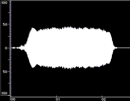
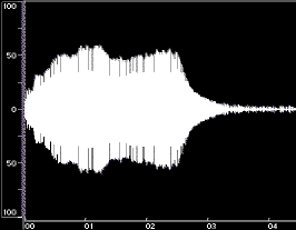
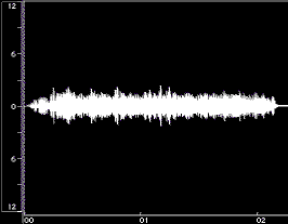
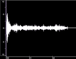
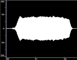
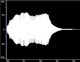
Figure 1 shows time-domain plots of two acoustic instrument tones and their syntheses resulting from Equation 1.
Figure 1: Time-domain plots of the original tone, noise-only synthesis (Ak set to 0), and complete synthesis for a flute tone (left) and a cello tone (right). The syntheses were done using open-source Loris, with bandwidth-enhanced oscillators described in Equation 1. Low frequency rumble present in the original recordings was omitted from syntheses. The vertical axes are percent amplitude, the horizontal axes are time in seconds; the scales are modified for the noise-only syntheses. These plots were made using BIAS Peak.
Figure 2 shows spectrogram plots of a flute tone and its synthesis with and without noise envelope contributions.
Figure 2: Spectrogram plots of a flute recording, sine-only synthesis (Nk set to 0), and complete synthesis using Equation 1. The low-frequency rumble present in the original flute recording was omitted from the synthesis. The horizontal axes are frequency in kHz, the vertical axes are relative amplitude, and the front-to-back axes are approximately 2.3 seconds. These plots were made using SoundMaker by Alberto Ricci.
Please use headphones to critically listen to the following from Loris:
Sound Example 1: High-quality synthesis of a flute (D4) of Figure 1. The whistling at the beginning is in the original, and is faithfully synthesized.
Sound Example 2: Harmonic partials only. This requires only 38 sine oscillators, because it excludes partials that are contributing to “noise” as opposed to “harmonics”. As expected, the sound is “thin”, and has “tinkly” artifacts caused by partials cutting in and out.
Sound Example 3: Noise-only. This includes all the partials that are non-harmonic and contribute to “noise”. In other words, this is the same as (1) minus the sine wave oscillators heard in (2). Unlike the “residual” in the Serra and Smith method (1990), this sounds unpitched.
Sound Example 4: Bandwidth-Enhanced Oscillators -- this is synthesis with only one oscillator per harmonic like (2), but in addition to an amplitude envelope each sine oscillator also has a noise-modulation-envelope to dynamically widen bandwidth. The bandwidth helps capture the noise in (3). Compare (4) to (1) -- they are quite similar, despite (4) representing the sound with much less data and requiring much less processing power for synthesis and manipulation.
4 Transients, Reassignment, and Loris
The analysis and representation of transients is a well-known problem for additive synthesis. The onset of a sound, in particular, is psychoacoustically important (Berger 1964, Saldanha and Corso 1964) and is difficult to analyze with sufficient time accuracy. The time-domain shape of an attack is distorted because the window used in the analysis of the sound cannot be perfectly time-localized.
Conventional additive analysis performs a sequence of short-time Fourier transforms. The time domain signal is windowed, with overlapping windows used for successive transforms. The result of each transform is mapped to the time at the center of each window. If a window of data is centered just before the onset of a sound, the left (early) samples in the window precede the attack and the right (later) samples in the window include the attack. If this situation is not explicitly detected, the attack is blurred. The time-domain shape of transients is distorted even if, at each window, the analysis guarantees phase-correctness of each partial.
Verma, Levine, and Meng (1997) developed a transient analysis that preserves the time-domain shape; their analysis may be used together with a deterministic sine model and a stochastic noise model. In our implementation based on homogenous envelope parameter streams, we avoid a separate transient model by incorporating the method of reassignment into the Loris analysis.
The method of reassignment has been used for sharpening blurred speech spectrograms (Auger and Flandrin 1995, Plante, Meyer, and Ainsworth 1998). Each point of the spectrogram is mapped in time and frequency to represent the distribution of the energy in time and frequency more accurately. Rather than associating each spectrogram point with the center of gravity of the window, the method of reassignment associates each spectrogram point with the center of gravity of energy.
We use the method of reassignment to sharpen transients in the Loris analysis. The method of reassignment helps avoid much of the blurring of transients that would occur due to the length of our analysis window. The analysis performs reassigned transforms on a sequence of overlapping windows. Each reassigned transform has a two-dimensional result, since each magnitude point has its own time and frequency coordinate. A sequence of overlapping windows produces a sequence of overlapping time-frequency results. When all these are superimposed, a complete time-frequency surface is obtained. The analysis finds significant ridges is this time-frequency surface, with each ridge corresponding to a bandwidth-enhanced partial that may be synthesized with Equation 1.
Figure 6 shows a Loris plot of a fortissimo cello tone analyzed using the method of reassignment. The plot shows the first 11 of (approximately) 120 significant ridges detected in the time-frequency surface. The plot shows the first 140 milliseconds of the tone, which include all the attack transients.
Figure 3: Portion of a Loris analysis of a low cello tone (first 143 ms, frequencies to 781 Hz). Lines indicate ridges present in the time-frequency surface during analysis. Dots indicate time-frequency data points that make up the ridges; all other data points from the time-frequency surface are not shown. Note that the dots are not at regular intervals due to the method of reassignment. Each ridge corresponds to a partial, and is synthesized with a bandwidth-enhanced oscillator as shown in Equation 1. Darker lines correspond to higher ridges (larger Ak), and blue tint indicates wider ridges (larger Nk).
For each analysis window, a series of magnitudes is computed, just as in traditional short-time Fourier transform methods. In addition, the method of reassignment transform produces coordinates in the time-frequency surface for each magnitude (Kodera, Gendrin, and Villedary 1978). The following two subsections describe how the reassigned transform may be computed using three short-time Fourier transforms.
Computing Time Coordinates
The time coordinate tr is computed by (Kodera, Gendrin, and Villedary 1978, Flandrin 1993, Auger and Flandrin 1995):
Equation 2
The denominator is a short-time Fourier transform (STFT) of the input centered at t, using the following definition:
Equation 3
The numerator is similar to the denominator, but the analysis window is multiplied by the time variable, s. This has the effect of weighting data in the right (later) part of the STFT window differently than the data in the left (earlier) part of the window. The ratio in Equation 2 computes the center of gravity of the energy. The time coordinate in the time-frequency surface, tr , is computed by adding the time at the center of the window t and the ratio of the time-weighted transform to the traditional, unweighted transform. If all the data are in the right of the window, tr is greater than t; if all the data are in the left of the window, tr is less than t.
If we define a new window function which incorporates the time weighting:
Equation 4
then the equation can be rewritten:
Equation 5
It should be noted here that the method of reassignment does not address phase issues. In spectrograms phase data are ignored, but in Loris phase information is essential to the analysis. In traditional short-time transform methods the phase is computed at the center of the window; in Loris the phase is computed at the time coordinate obtained from the method of reassignment.
The time coordinate and its derivative aid our analysis in identifying exact starting point and amplitude evolution of partials. In addition, the temporal variance s2x(s) can be used to further improve temporal shape.
Computing Frequency Coordinates
In addition to a time coordinate, the method of reassignment also yields a frequency coordinate. The equation for determining the frequency coordinate is as follows (Kodera, Gendrin, and Villedary 1978, Flandrin 1993, Auger and Flandrin 1995):
Equation 6
The equation is similar to that for the time coordinate (Equation 2), except that the numerator now has a frequency-weighting function instead of a time-weighting function. We can define a new window function that incorporates this frequency-weighting function (this corresponds to a derivative in the time domain):
Equation 7
We can rewrite the equation for finding the frequency coordinate using STFTs:
Equation 8
In practice, refining the frequency estimate by parabolic interpolation works well (Smith and Serra 1987); we have yet to make a detailed comparison of the reassignment approach and the parabolic interpolation approach to refining frequency. In Loris we implement a magnitude correction based on the frequency coordinate.
5 Navigating Source Timbres: Timbre Control Space
Our intention is to implement a real-time additive synthesizer that uses a large number of recordings to provide the timbre source material for synthesis. A timbre control space gives the performer a simple and intuitive way to navigate the available timbres (Haken 1992).
We define timbre as the characteristics of a sound, other than its pitch and loudness, which distinguish it from other sounds. Two sounds with the same fundamental frequency and the same amplitude often have different timbres, even if they are produced by one instrument. For example, bowing a cello near the fingerboard results in a mellower timbre than bowing near the bridge.
In our synthesizer, we would like timbre to vary with pitch and loudness, as it does on an acoustic instrument. The timbre of a loud note on a cello, for instance, is not an amplitude-scaled version of the timbre of a quiet cello note. Similarly, the timbre of a high-pitched cello note is not a frequency-shifted version of the timbre of a low-pitched cello note.
We define a three-dimensional timbre control space in which one dimension is pitch, another dimension is loudness, and the third dimension provides an additional timbre control. Moving along the pitch axis does not simply shift the spectral frequencies; instead, it gradually morphs from one pitch source timbre to another. Similarly, moving along the loudness axis does not simply scale the spectral amplitudes; instead, it gradually morphs between a quiet timbre and a louder timbre. Moving along the third axis produces yet other timbre changes, morphing between source timbres.
It should be noted here that our timbre control space is quite different from a timbre space derived from multidimensional perception experiments (Grey 1975, Wessel 1979, Risset and Wessel 1982). Our intention is merely to provide an intuitive and practical method for specifying the parameters used to generate each tone rather than to categorize the properties of the resultant timbres. It is quite possible, in fact, for nearby tones in the timbre control space to be located far apart in a timbre space.
We divide the three-dimensional timbre control space into cubes; neighboring cubes share one face. Figure 4 shows a cube of a timbre control space that was made from Loris analyses of four cello tones and four trombone tones. Each corner of the cube has a set of amplitude, frequency, and noise envelopes describing a source timbre. These eight sets of envelopes completely define this part of the timbre control space.
Figure 4: A cube in a timbre control space using source timbres from cello and trombone tones (Haken, Tellman, and Wolfe 1998).
The performer's finger motions on the Continuum Fingerboard control the x, y, and z position associated with any note. The timbre corresponding to a point located within a cube possesses characteristics of the source timbres at all eight corners of the cube. If the x, y, z of the performer's finger exactly corresponds to the center of the cube, the synthesized sound shares equally the characteristics of all eight source timbres. The finger's x, y, z may change over time, corresponding to crescendo, glissando, vibrato, or other articulations. As the finger's x, y, z moves toward one face of the cube, the four source timbres of that face contribute proportionally more to the synthesized timbre, while the four source timbres of the opposite face contribute proportionally less. If the finger's x, y, z is exactly at the center of one face of the cube, the synthesized timbre shares equally the characteristics of the four source timbres at the corners of that square. In this manner, the timbre control space provides a method for arranging the source timbres into a framework for describing new timbres.
Figure 5 shows an example of a complete three-dimensional timbre control space made of 24 cubes. The complete timbre control space is based on the analyses of 78 tones (39 trombone tones and 39 cello tones). When a note is played, the finger's x, y, and z location falls within one of the cubes in the timbre control space. For example, if the note's x location corresponds to a fourth octave F sharp and its zlocation corresponds to the forte dynamic, it falls into cube 16 in Figure 5. The synthesized sound is created by combining timbre characteristics of the pre-analyzed source recordings at the eight corners of cube 16.
Figure 5: A timbre control space made up of 24 cubes, based on 78 source timbres (39 trombone tones and 39 cello tones). The cubes have unequal widths because the pitches of the source recordings were not equally spaced.
If the x, y, z coordinate gradually changes during a note, this corresponds to a gradual change of location, usually within a cube of the timbre control space. If the x, y, z coordinate changes greatly during a note, the timbre control space location of the sound is likely to travel through the face of one cube into a neighboring cube. In all cases the timbre changes associated with changing x, y, and z are smooth and continuous. This aspect--continuous timbre change--is the motivation for using additive synthesis in place of traditional sampling synthesis.
Creating a New Timbre Control Space
The simplest timbre control space is one cube based on the analyses of eight recorded sounds. More timbre variation is possible when the timbre control space consists of several cubes. Analyses of recordings at perfectly corresponding pitches, loudnesses, and manner of performance are needed to define the corners of each cube in a timbre control space. In practice, it is time-consuming to create a timbre control space because it is difficult to get such recordings. To some extent, side-by-side listening comparisons together with editing operations (amplitude multiplication, pitch shifting, time compression, expansion, or cutting) can be used to reduce the differences between the recordings (Grey 1975). Also, non-real-time morphing of recordings irregularly placed in a timbre control space can be used to produce the timbres at regularly-placed cube corners. Since the perceived similarity between timbres depends on many psychoacoustic effects, this process cannot be completely automated, and building a new timbre control space remains a time consuming process. Each timbre control space defines a very different sound and feel for the performer, so learning to play in a new timbre control space is a major undertaking as well.
The three-dimensional timbre control space can be divided into a collection of tetrahedrons, rather than a collection of cubes (Goudeseune 1999). Then three-dimensional morphing is between four timbres instead of our eight. Also, the choice of three control dimensions in the timbre control space is arbitrary. Any number of control dimensions could be defined. The meaning of any control dimension depends only on what source recordings are used, and where the source recordings are assigned in the timbre control space.
6 Implementation of Sound Morphing
Over the years many researchers have investigated sound morphing. Grey (1975) did a study involving morphing between two original sounds to create new intermediate sounds. Schindler (1984) described sounds as a hierarchical tree of timbre frames, and discussed a morphing algorithm that operates on this representation. Time-varying filters have been used to combine timbres (Peterson 1975, Depalle and Poirot 1991). With multiple wavetable synthesis, sound morphing can be implemented as a straight mix because all harmonics are phase-locked (Horner, Beauchamp, and Haken 1993).
Real-time Sound Morphing using Parameter Streams
A finger's x, y, z on the Continuum Fingerboard determines a position within one of the cubes that make up the timbre control space. Each corner of the cube corresponds to a source recording pre-analyzed using our Loris analysis program. Amplitude, frequency, phase, and noise envelopes are available for each partial of each source timbre. Weighted averages of these envelopes at the corners of one cube are used to synthesize the sound. This processing is straightforward to implement in real time with weighted averages of envelope parameter streams.
The weighted averages are continually computed according to the sound's location within the cube. Each Ak, Nk, and Fk in Equation 1 is a combination of the envelopes at the corners of the cube. If we normalize the x, y, z position within the cube such that X, Y, and Z are between 0 and 1, then the interpolation weights for each corner of the cube are:
Equation 9
To avoid problems with roundoff errors, W7 is computed by subtracting the sum of the other weights from 1.
These weights implement a rectilinear distance measure to the corners of the cube, not a Cartesian measure. We use the rectilinear measure to avoid discontinuities when the finger's x, y, z changes such that the coordinates in the timbre control space travel through the face of a cube into an adjacent cube.
The weights from Equation 9 are used to compute the Ak, Nk, and Fk from Equation 1:
Equation 10
where
t is the sample number,
tau(t) is the running time index into time-normalized partial envelopes,
k is the partial number in the sound,
alphak,q is partial k's amplitude envelope in the source timbre at corner q,
betak,q is partial k's noise envelope in the source timbre at corner q,
phik,q is partial k's log frequency envelope in the source timbre at corner q,
Wk is the weighting for corner q of the cube based on the current x, y, z location,
Ak is partial k's real-time morphed amplitude envelope,
Fk is partial k's real-time morphed log frequency envelope,
Nk is partial k's real-time morphed noise envelope.
Time Dilation using Time Envelopes
Source timbres often have differing attack and release rates, as well as differing time characteristics for their sustained portions. If the morphing process simply averaged the envelopes of the source timbres, the resultant sound would have averaged attack peaks rather than a single attack of intermediate speed. To facilitate combining timbres of sounds with different rates of time evolution, we apply a temporal pre-normalization to the analyses and produce a corresponding time envelope (Haken, Tellman, and Wolfe 1998). At synthesis time, the performance parameters determine if we traverse the analysis at a rate faster or slower than specified by the time envelope.
At synthesis time we compute:
Equation 11
where
t is the sample number,
tau(t) is the index into the time-normalized partial envelopes at sample number t,
Wq is the weighting for corner q of the cube based on the current x, y, z location,
Eq is the time envelope (time expansion function) for corner q of the cube.
Source recordings that contain vibrato also present timing problems. Care must be taken when morphing between differing vibrato rates to avoid producing an irregular vibrato. Equation 11 allows us to produce a regular vibrato, because we manipulate time-normalized envelopes which have normalized vibrato periods, thus performing an important part of vibrato morphing described by Tellman, Haken, and Holloway (1995). For the Continuum Fingerboard, however, source recordings normally do not contain vibrato. If the source timbres included vibrato, the synthesized sound would have vibrato without movement of the performer's fingers.
References
F. Auger and P. Flandrin, "Improving the Readability of Time Frequency and Time Scale Representations by the Reassignment Method," IEEE Transactions on Signal Processing, vol. 43 (1995), pp. 1068 - 1089.
K. W. Berger, "Some Factors in the Recognition of Timbre," Journal of the Acoustical Society of America, vol. 36 (October 1964), pp. 1888 - 1891.
P. Depalle and G. Poirot, "Svp: A Modular System for Analysis, Processing and Synthesis of Sound Signals," Proceedings of the 1991 International Computer Music Conference, International Computer Music Association, San Francisco, pp. 161 - 164.
K. Fitz and L. Haken, "Bandwidth-enhanced Sinusoidal Modeling in Lemur," Proceedings of the 1995 International Computer Music Conference, International Computer Music Association, San Francisco, pp. 154 - 156.
K. Fitz and L. Haken, "Sinusoidal Modeling and Manipulation Using Lemur," Computer Music Journal, vol. 20, no. 4 (1996), pp. 44 - 59.
K. Fitz and L. Haken, "Improving Additive Sound Modeling Using the Method of Reassignment," submitted to the 1999 IEEE Workshop on Applications of Signal Processing to Audio and Acoustics, New Paltz, New York.
K. Fitz and L. Haken, "On the Use of Time-Frequency Reassignment in Additive Sound Modelling,", Journal of the Audio Engineering Society, vol. 50, no. 11 (November 2002), pp. 879-893.
P. Flandrin, Temps-Frequence, Paris, France: Hermes, 1993, p. 223.
C. O. Goudeseune, "Composing with Parameters for Synthetic Instruments," Ph.D. thesis, Dept. of Music, University of Illinois, Urbana-Champaign, IL (to be completed 1999).
J. M. Grey, "An Exploration of Musical Timbre," Ph.D. thesis, Dept. of Psychology, Dept. of Music Report STAN-M-2, Stanford University, Stanford, CA (1975).
J. M. Grey, "Multidimensional Perceptual Scaling of Musical Timbre," Journal of the Acoustical Society of America, vol. 61 (1977), pp. 1270 - 1277.
L. Haken, "Computational Methods for Real-time Fourier Synthesis," IEEE Transactions on Signal Processing, vol. 40, no. 9 (September 1992), pp. 2327 - 2329.
L. Haken, "Real-time Timbre Modifications using Sinusoidal Parameter Streams," Proceedings of the 1995 International Computer Music Conference, International Computer Music Association, San Francisco, pp. 162 - 163.
L. Haken, R. Abdullah, and M. Smart, "The Continuum: A Continuous Music Keyboard," Proceedings of the 1992 International Computer Music Conference, International Computer Music Association, San Francisco, pp. 81 - 84.
L. Haken, E. Tellman, and P. Wolfe, "An Indiscrete Music Keyboard," Computer Music Journal, vol. 22, no. 1 (Spring 1998), pp. 30 - 48.
K. Hebel and C. Scaletti, "A Framework for the Design, Development, and Delivery of Real-time Software-based Sound Synthesis and Processing Algorithms," Audio Engineering Society, Preprint Number 3874 (A-3), San Francisco (1994).
A. Horner, J. Beauchamp, and L. Haken, "Methods for Multiple Wavetable Synthesis of Musical Instrument Tones," Journal of the Audio Engineering Society, vol. 41, no. 5 (May 1993), pp. 336 - 356.
K. Kodera, R. Gendrin, and C. de Villedary, "Analysis of Time-Varying Signals with Small BT Values," IEEE Transactions on Acoustics, Speech, and Signal Processing, vol. ASSP-26, no. 1 (February 1978), pp. 64 - 76.
R. Maher, "An Approach to the Separation of Voices in Composite Music Signals," Ph.D. thesis, Dept. of Electrical and Computer Engineering, University of Illinois at Urbana-Champaign, Urbana, IL (1989).
R. J. McAulay and T. F. Quatieri, "Speech Analysis/Synthesis Based on a Sinusoidal Representation," IEEE Transactions on Acoustics, Speech, and Signal Processing, vol. ASSP-34 (1986), pp. 744 - 754.
T. L. Peterson, "Vocal Tract Modulation of Instrumental Sounds by Digital Filtering," Proceedings of the Second Annual Music Computation Conference (1975), pp. 33 - 41.
F. Plante, G. Meyer, and W. A. Ainsworth, "Improvement of Speech Spectrogram Accuracy by the Method of Reassignment," IEEE Transactions on Speech and Audio Processing, vol. 6, no. 3 (May 1998), pp. 282 - 287.
J.-C. Risset and D. Wessel, "Exploration of Timbre by Analysis and Synthesis," The Psychology of Music, Diana Deutsch, ed., Academic Press, Inc., New York, pp. 26 - 58, 1982.
E. L. Saldanha and J. F. Corso, "Timbre Cues for the Recognition of Musical Instruments," Journal of the Acoustical Society of America, vol. 36 (November 1964), pp. 2021 - 2026.
C. Scaletti, "Kyma: An Object-oriented Language for Music Composition," Proceedings of the 1987 International Computer Music Conference, International Computer Music Association, San Francisco, pp. 49 - 56.
K. W. Schindler, "Dynamic Timbre Control for Real-Time Digital Synthesis," Computer Music Journal, vol. 8 (1984), pp. 28 - 42.
X. Serra and J. O. Smith, "Spectral Modeling Synthesis: A Sound Analysis/Synthesis System Based on a Deterministic plus Stochastic Decomposition," Computer Music Journal, vol. 14, no. 4 (1990), pp. 12 - 24.
J. O. Smith and X. Serra, "PARSHL: An Analysis/Synthesis Program for Non-Harmonic Sounds Based on a Sinusoidal Representation," Proceedings of the 1987 International Computer Music Conference, International Computer Music Association, San Francisco, pp. 290 - 297.
E. Tellman, L. Haken, and B. Holloway, "Morphing Between Timbres with Different Numbers of Features," Journal of the Audio Engineering Society, vol. 43, no. 9 (1995), pp. 678 - 689.
T. S. Verma, S. N. Levine, T. H. Y. Meng, "Transient Modeling Synthesis: A Flexible Analysis/Synthesis Tool for Transient Signals," Proceedings of the 1997 International Computer Music Conference, International Computer Music Association, San Francisco, pp. 164 - 167.
D. Wessel, "Timbre Space as a Musical Control Structure," Computer Music Journal, vol. 3, no. 2 (1979), pp. 45 - 52.
![Eq01[1].gif](https://images.squarespace-cdn.com/content/v1/5b5353de506fbe04915e9b38/1563047281035-5JMNZO1345M24RLDJVGN/Eq01%5B1%5D.gif)
![Spec_flute_orig[1].gif](https://images.squarespace-cdn.com/content/v1/5b5353de506fbe04915e9b38/1563047396173-MSR7MA5DG4VWV077I3MF/Spec_flute_orig%5B1%5D.gif)
![Spec_flute_sine[1].gif](https://images.squarespace-cdn.com/content/v1/5b5353de506fbe04915e9b38/1563047409837-ZNWRDQLW8FL7E6EP8XXJ/Spec_flute_sine%5B1%5D.gif)
![Spec_flute_complete[1].gif](https://images.squarespace-cdn.com/content/v1/5b5353de506fbe04915e9b38/1563047421798-8ZKW6UIMNV7B2RQPKTYO/Spec_flute_complete%5B1%5D.gif)
![Loris_cello[1].gif](https://images.squarespace-cdn.com/content/v1/5b5353de506fbe04915e9b38/1563047471160-7KIO6J75BE8NPUBRFT85/Loris_cello%5B1%5D.gif)
![Eq02[1].gif](https://images.squarespace-cdn.com/content/v1/5b5353de506fbe04915e9b38/1563047528779-Y1TL1L0REZBQZOJ1SK0P/Eq02%5B1%5D.gif)
![Eq03[1].gif](https://images.squarespace-cdn.com/content/v1/5b5353de506fbe04915e9b38/1563047547688-M0HHT5Y2LC42K6QBR23K/Eq03%5B1%5D.gif)
![Eq04[1].gif](https://images.squarespace-cdn.com/content/v1/5b5353de506fbe04915e9b38/1563047566378-5A820P5NUEVEXRDWSCZ0/Eq04%5B1%5D.gif)
![Eq05[1].gif](https://images.squarespace-cdn.com/content/v1/5b5353de506fbe04915e9b38/1563047586965-VQWH70ACY97JPU7R23IT/Eq05%5B1%5D.gif)
![Eq06[1].gif](https://images.squarespace-cdn.com/content/v1/5b5353de506fbe04915e9b38/1563047601102-PJ114JB42UNC7YV27CSC/Eq06%5B1%5D.gif)
![Eq07[1].gif](https://images.squarespace-cdn.com/content/v1/5b5353de506fbe04915e9b38/1563047612301-QBOZZ5CRLCSQO6JK1LVD/Eq07%5B1%5D.gif)
![Eq08[1].gif](https://images.squarespace-cdn.com/content/v1/5b5353de506fbe04915e9b38/1563047618626-BNLY6DNB1U8RMN54N4WE/Eq08%5B1%5D.gif)
![Cube_single[1].gif](https://images.squarespace-cdn.com/content/v1/5b5353de506fbe04915e9b38/1563047630843-VL2CG8TE8LW4CTZA4RN2/Cube_single%5B1%5D.gif)
![Cube_multiple[1].gif](https://images.squarespace-cdn.com/content/v1/5b5353de506fbe04915e9b38/1563047639654-CBGS6KR8XKJL4YP8SENC/Cube_multiple%5B1%5D.gif)
![Eq09[1].gif](https://images.squarespace-cdn.com/content/v1/5b5353de506fbe04915e9b38/1563047651252-OQ3FPDTC6AKUKXR2Y7C4/Eq09%5B1%5D.gif)
![Eq10[1].gif](https://images.squarespace-cdn.com/content/v1/5b5353de506fbe04915e9b38/1563047658768-R5DQD4RUJKMNMQ4XDESI/Eq10%5B1%5D.gif)
![Eq11[1].gif](https://images.squarespace-cdn.com/content/v1/5b5353de506fbe04915e9b38/1563047667934-UFF7JHZJM92E7B62GMU3/Eq11%5B1%5D.gif)